Back to Contents Page
Dell™ PowerEdge™ 6600 Systems
Installation and
Troubleshooting Guide
If your system is not working as expected, begin troubleshooting by using the procedures in this section. This section guides you through some initial checks and procedures that can solve basic system problems and provides troubleshooting procedures for components inside the system. Before you start any of the procedures in this section, take the following steps:
- Read the "Safety Instructions" in your System Information document.
- Read "Running the System Diagnostics" for information about running diagnostics.
- Get the key to the system's keylock and back cover.
The procedures in this guide require that you remove the cover and work inside the system. While working inside the system, do not attempt to service the system except as explained in this guide and elsewhere in your system documentation. Always follow the instructions closely. Make sure to review all of the procedures in "Safety Instructions" in your System Information document.
Working inside the system is safe—if you observe the following precautions.

|
CAUTION: The power supplies in this system produce high voltages and energy
hazards, which can cause bodily harm. Only trained service technicians are
authorized to remove the system cover and access any of the components inside
the system.
|
 |
NOTICE: See "Protecting Against Electrostatic Discharge" in the safety instructions in your
System Information document before performing any procedure which requires you to open the
cover.
|
Before you perform any of the procedures, ensure that the following components are securely and properly installed:
- Power cables
- Cables to external devices, such as monitor, mouse, and keyboard
- Microprocessor tray
Improperly set switches, controls, and loose or improperly connected cables are the most likely source of problems for the system, monitor, or other peripherals (such as a printer, keyboard, mouse, or other external equipment). A quick check of all the switches, controls, and cable connections can easily solve these problems. See Figure 2-3 for the back-panel features and connectors.
- Turn off the system, including any attached peripherals, and disconnect all power
cables from their electrical outlets.
- If the system is connected to a PDU, turn the PDU off and then on again.
If the PDU is not receiving power, plug it into another electrical outlet. If it still is not receiving power, try another PDU.
- Reconnect the system to the electrical outlet or PDU.
- Is the monitor working properly?
See "Troubleshooting the Video Subsystem."
- Is the keyboard working properly?
See "Troubleshooting the Keyboard."
- Are the mouse and printer working properly?
See "Troubleshooting the Basic I/O Functions."
Looking at and listening to the system is important in determining the source of a problem. Look and listen during the system's start-up routine for the indications described in Table 5-1.
Figure 5-1 shows the rack and tower versions of your system. The illustrations in this document are based on the tower version with the system laying on its right side.
Figure 5-1. System Orientation
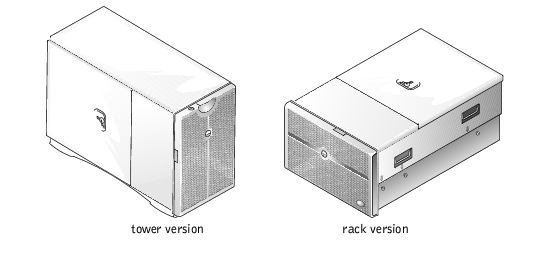
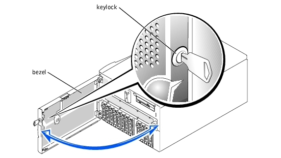
The bezel has status and caution indicators. Opening or removing the bezel provides access to the power switch, diskette drive, CD drive, and hard drive(s). You must open the bezel and remove the system covers to gain access to internal components.
- Using the system key, unlock the bezel if it is locked.
- Pull the bezel away from the system so that it is perpendicular to the system (see
Figure 5-2).
Figure 5-2. Opening the Bezel
- Swing the bezel closed until it snaps into place.
- Using the system key, lock the bezel.
The system is enclosed by a bezel and two covers. To upgrade or troubleshoot the system, remove the system covers to gain access to internal components. The back cover must be removed before removing the front cover.
- Using the system key, unlock the back cover if it is locked.
- Observe the precautions in "Safety First—For You and Your System."
- Loosen the thumbscrew that secures the back cover to the chassis (see Figure 5-3).
Figure 5-3. Removing and Replacing the Back Cover
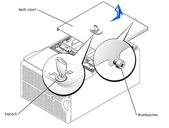
- Slide the back cover backward and grasp the cover at both ends.
- Carefully lift the cover away from the system.
- Check that no tools or parts are left inside the system and that any cables are routed so
that they will not be damaged by the cover.
- Align the cover with the cover alignment notches on the sides of the chassis, and slide
the cover forward (see Figure 5-3).
- Tighten the thumbscrew that secures the cover to the chassis (see Figure 5-3).
- Using the system key, lock the back cover.
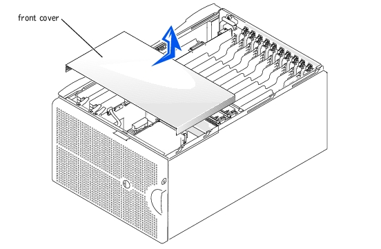
- Remove the back cover (see "Removing the Back Cover").
- Slide the front cover backward and grasp the cover at both ends (see Figure 5-4).
- Carefully lift the cover away from the system.
Figure 5-4. Removing and Replacing the Front Cover
- Check that no tools or parts are left inside the system and that any cables are routed so
that they will not be damaged by the cover.
- Align the cover with the cover alignment notches on the sides of the chassis, and slide
the cover forward (see Figure 5-4).
- Replace the back cover (see "Replacing the Back Cover").
This section provides troubleshooting procedures for equipment that connects directly to the I/O riser card, such as the monitor, keyboard, or mouse. Before you perform any of the procedures, see "External Connections."
- Monitor
- Monitor interface cable
- Video memory
- Video logic
- Check the system and power connections to the monitor.
- Determine whether the system has a remote access card and a video expansion card
installed.
The system supports only the embedded video when using a remote access card.
If a video expansion card is not installed, go to step 3.
If a video expansion card is installed, remove the video card (see "Removing an Expansion Card" in "Installing System Options"). If the problem persists, go to step 3.
- Run the video tests in the system diagnostics.
If the tests run successfully, the problem is not related to video hardware. Go to "Finding Software Solutions."
If the tests did not run successfully, see "Getting Help" for instructions on obtaining technical assistance.
- System error message indicates a keyboard problem
- Look at the keyboard and the keyboard cable for any signs of damage.
If the keyboard and its cable appear to be free of physical damage and the keys work, go to step 3.
If the keyboard or its cable are damaged, continue to step 2.
- Swap the faulty keyboard with a working keyboard.
If the problem is resolved, the keyboard must be replaced (see "Getting Help" for instructions on obtaining technical assistance).
- Run the keyboard test in the system diagnostics.
If you can use the keyboard to select the keyboard test, go to step 4.
If the test did not run successfully, see "Getting Help" for instructions on obtaining technical assistance.
- Swap the faulty keyboard with a working keyboard.
If the problem is resolved, the faulty keyboard must be replaced.
If the problem is not resolved, the keyboard controller on the I/O riser card is faulty (see "Getting Help" for instructions on obtaining technical assistance).
- System error message indicates a mouse problem
- Look at the mouse and the mouse cable for any signs of damage.
- Click each button on the mouse.
If the mouse and its cable appear to be free of physical damage and the buttons work, go to step 4.
If the mouse or its cable are damaged, continue to step 3.
- Swap the faulty mouse with a working mouse.
If the problem is resolved, the mouse must be replaced (see "Getting Help" for instructions on obtaining technical assistance).
- Run the pointing devices test in the system diagnostics.
If the problem is resolved, the faulty mouse must be replaced.
If the problem is not resolved, the controller on the I/O riser card is faulty (see "Getting Help" for instructions on obtaining technical assistance).
- System error message indicates an I/O port problem
- Device connected to the port is not working
- Enter the System Setup program (see "Using the System Setup Program" in the User's
Guide for instructions) and check the Serial Port 1 setting.
If the communications port is set to Off, go to step 3.
If the communications port is not set to Off, continue to step 2.
- Change the Serial Port 1 setting to Auto; then reboot the system.
- Check the settings in the System Setup program.
See "Using the System Setup Program" in the User's Guide for instructions. If the settings are correct, go to step 5.
- Change the necessary settings in the System Setup program. If the port problem is
confined to a particular application program, see the application program's
documentation for specific port configuration requirements.
- Reboot the system from the diagnostics diskette, and run the serial port test in the
system diagnostics.
If the test did not run successfully, see "Getting Help" for instructions on obtaining technical assistance.
If the test runs successfully but the problem persists, see "Troubleshooting a Serial I/O Device."
- Device connected to the serial port is not working
- Open the front bezel (see "Opening the Bezel").
- Turn off the system and any peripheral devices connected to the serial port.
- Swap the interface cable with a known working cable.
If the problem is resolved, the interface cable must be replaced (see "Getting Help" for instructions on obtaining technical assistance).
- Turn off power to the system and the serial device, and swap the device with a
comparable device.
- Turn on the system and the serial device.
If the problem is resolved, the serial device must be replaced.
If the problem is not resolved, see "Getting Help" for instructions on obtaining technical assistance.
- System error message indicates problem
- Device connected to the port is not working
- Enter the System Setup program and ensure that the USB ports are enabled (see
"Using the System Setup Program" in the User's Guide for instructions).
- Open the front bezel (see "Opening the Bezel").
- Turn off the system and any USB devices.
If there is only one USB device connected to the system, go to step 6.
- Disconnect all USB devices, and connect the malfunctioning device to the other USB
port.
- Turn on the system and the reconnected device.
If the problem is resolved, the USB port may be defective (see "Getting Help" for instructions on obtaining technical assistance).
- If possible, swap the interface cable with a known working cable.
If the problem is resolved, the interface cable must be replaced (see "Getting Help" for instructions on obtaining technical assistance).
- Turn off the system and the USB device, and swap the device with a comparable
device.
- Turn on the system and the USB device.
If the problem is resolved, the USB device must be replaced.
If the problem is not resolved, see "Getting Help" for instructions on obtaining technical assistance.
- NICs cannot communicate with the network
- Check the appropriate indicator on the NIC connector (see Figure 2-6).
A green indicator shows that the adapter is connected to a valid link partner. A blinking amber indicator shows that network data is being sent or received.
- If the link indicator is not on, check all cable connections.
- Try changing the auto-negotiation setting, if possible.
- Try another port on the switch or hub.
If you are using a NIC expansion card instead of the integrated NICs, see the documentation for the NIC card.
- If the indicator does not light, the network driver files might be damaged or deleted.
Check the drivers, and remove and reinstall the drivers if applicable.
You must reboot your system for the reinstalled drivers to become active.
- Ensure that the appropriate drivers are installed and the protocols are bound.
- Enter the System Setup program and confirm that the NICs are enabled (see "Using
the System Setup Program" in the User's Guide).
- Ensure that the NICs, hubs, and switches on the network are all set to the same data
transmission speed.
- Ensure that all network cables are of the proper type and do not exceed the specified
length. For more information, see "Network Cable Requirements" in the User's Guide.
In Figure 5-5, the system covers are removed and the bezel is opened to provide an interior view of the system.
Figure 5-5. Inside the System
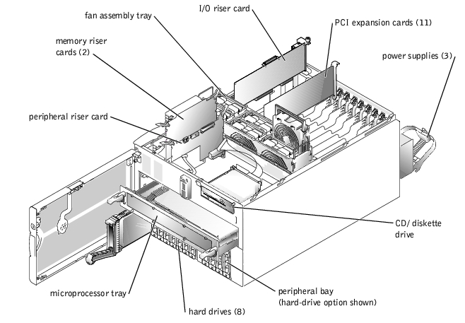
The I/O board can accommodate up to 11 PCI expansion cards (10 PCI or PCI-X cards at 64-bit/33–100 MHz and one PCI card at 32-bit/33 MHz). The system memory is contained on two separate riser cards that must be populated with at least two memory modules each for the system to operate. The peripheral bay provides space for four additional 1-inch SCSI hard drives or one tape drive.
The hard-drive bays provide space for up to eight 1-inch SCSI hard drives. These hard drives are connected to a RAID controller card through the SCSI backplane board.
The power distribution board (PDB) provides hot-plug logic and power distribution for the system. Your system can utilize an AC module or an optional, integrated, redundant AC power module to provide AC current to the hot-pluggable power supplies. The AC module is used when a redundant AC power source is not required. The integrated redundant AC power module enables your system to use two AC inputs. Your system can operate on either of these inputs and automatically switches from a failing AC power source. The three hot-pluggable power supplies slide into connectors mounted on the PDB and provide power to the system board, SCSI backplane board, and internal peripherals.
For non-SCSI drives such as the diskette drive and CD drive, an interface cable connects the interposer board, attached to the CD/diskette drive tray, to the peripheral riser card. For SCSI devices, interface cables connect externally accessible SCSI devices and the SCSI backplane board to a SCSI host adapter on either the I/O riser card or an expansion card (for more information, see "Installing Drives").
During an installation or troubleshooting procedure, you may be required to change a jumper. For information on jumpers, see "Jumpers and Connectors."
The optional systems management applications monitor critical system voltages and temperatures, the system cooling fans, and the status of the SCSI hard drives in the system. Alert messages appear in the alert log window. For information about the alert log window and options, see your systems management software documentation.
- Liquid spills
- Splashes
- Excessive humidity
- Turn off the system, including any attached peripherals, and disconnect the system
from the electrical outlet.
- Remove the back cover (see "Removing the Back Cover").
- Remove the front cover (see "Removing the Front Cover").
- Remove all expansion cards installed in the system (see "Removing an Expansion
Card" in "Installing System Board Options").
- Let the system dry thoroughly for at least 24 hours.
- Replace the system covers, reconnect the system to the electrical outlet, and turn on
the system.
If the system does not start up properly, see "Getting Help" for instructions on obtaining technical assistance.
- If the system starts up normally, shut down the system and reinstall all expansion cards
that were removed in step 4 (see "Installing an Expansion Card" in "Installing System
Board Options").
- Run the system board tests in the system diagnostics to confirm that the system is
working properly.
If the tests did not complete successfully, see "Getting Help" for instructions on obtaining technical assistance.
- System dropped or damaged
- Ensure that all cables are properly connected.
- Ensure that all components are properly installed and are free from damage.
- Run the system board tests in the system diagnostics.
If the tests did not complete successfully, see "Getting Help" for instructions on obtaining technical assistance.
- Error message shows a problem with the battery
- System Setup program loses system configuration information
- System date and time do not stay current
The system battery maintains system configuration, date, and time information in a special section of memory when you turn off the system. The operating life of the battery ranges from 2 to 5 years, depending on how you use the system (for example, if you keep the system on most of the time, the battery gets little use and thus lasts longer). You may need to replace the battery if an incorrect time or date is displayed during the boot routine.
You can operate the system without a battery; however, the system configuration information maintained by the battery in NVRAM is erased each time you remove power from the system. Therefore, you must re-enter the system configuration information and reset the options each time the system boots until you replace the battery.
- Re-enter the time and date through the System Setup program (see "Using the System
Setup Program" in the User's Guide for instructions).
- Turn off and disconnect the system from the electrical outlet for a few hours.
- Reconnect the system to the electrical outlet and turn the system on again.
- Enter the System Setup program.
If the date and time are not correct in the System Setup program, replace the battery (see "System Battery").
If the problem is not resolved by replacing the battery, see "Getting Help" for instructions on obtaining technical assistance.
 |
NOTE: Some software may cause the system time to speed up or slow down. If the
system seems to operate normally except for the time kept in the System Setup
program, the problem may be caused by software rather than by a defective battery.
|
|
NOTE: If the system is turned off for long periods of time (weeks or months), the
NVRAM may lose its system configuration information. This situation is not caused by
a defective battery.
|
- System caution indicator is amber
- Front-panel status LCD indicates a problem with power supply
- Power-supply fault indicator signifies a problem
- Locate the faulty power supply.
The power supply's fault indicator is lit (see Figure 2-5).
|
NOTICE: The power supplies are hot-pluggable. The system requires two power supplies to be
installed for the system to operate normally. Remove and replace only one power supply at a time
in a system that is powered on.
|
- Squeeze the power-supply handle's release tab and rotate the handle down.
- Slide the power supply out until it clears the chassis.
- Slide the new power supply into the chassis until it stops.
- Rotate the handle up until it snaps into place.
If the problem persists, see "Getting Help" for instructions on obtaining technical assistance.
Cooling of the entire system as well as individual components can be affected by the following:
- Ambient temperature surrounding the system is too high.
- Airflow intake and output are obstructed.
- Cables inside the system obstruct cooling fan intake or output.
- Systems management software issues a fan-related error message.
- An individual cooling fan has failed (see "Troubleshooting a Cooling Fan").
- Expansion-card filler brackets are not installed over empty expansion slots.
- A heat sink is not installed for each microprocessor.
|
NOTICE: If a microprocessor socket does not have a microprocessor installed, a heat sink
blank must be installed for that socket.
|
- System caution indicator is amber
- Front-panel status LCD indicates a problem with cooling
- Fan status indicator signifies a problem with the fan
- Systems management software issues a fan-related error message
- Remove the back cover (see "Removing the Back Cover").
- Locate the faulty fan.
|
NOTE: Each individual fan has a status indicator. If the fan is operating normally, the
indicator is green. If the fan is malfunctioning, the indicator is blinking amber.
|
|
NOTICE: The cooling fans are hot-pluggable. To maintain proper cooling while the system is
on, replace only one fan at a time.
|
- Remove the fan (see "Removing a Cooling Fan" in "Installing System Options").
- Reseat the fan in its compartment and ensure that the fan connector is firmly seated.
- If the problem is not resolved, install a new fan (see "Replacing a Cooling Fan" in
"Installing System Options").
- If the new fan does not operate, the fan connector is faulty (see "Getting Help" for
information on obtaining technical assistance).
|
NOTE: After installing a new fan, allow up to 30 seconds for the system to recognize
the fan and determine whether it is working properly.
|
- Error message indicates a microprocessor problem
- Error message indicates a microprocessor board problem
- Front-panel status LCD indicates a problem with microprocessors, VRMs, or the microprocessor board
- A heat sink is not installed for each microprocessor
|
NOTICE: If a microprocessor socket does not have a microprocessor installed, a heat sink
blank must be installed for that socket.
|
- Observe the precautions in "Safety First—For You and Your System."
- Turn off the system, including any attached peripherals, and disconnect the system
from its electrical outlet.
|
NOTICE: See "Protecting Against Electrostatic Discharge" in the safety instructions in your
System Information document.
|
- Remove the microprocessor tray (see "Removing the Microprocessor Tray").
- Ensure that VRMs are installed for each microprocessor and reseat the VRMs.
- Replace the microprocessor tray (see "Replacing the Microprocessor Tray").
- Reconnect the system to its electrical outlet and turn the system on, including any
attached peripherals.
- Run the Quick Tests in the system diagnostics.
If the problem persists, go to step 8.
- Turn off the system, including any attached peripherals, and disconnect the system
from its electrical outlet.
- Remove the microprocessor tray (see "Removing the Microprocessor Tray").
- Remove all microprocessors and VRMs except CPU1 and VRM1 (see "Adding or
Replacing a Microprocessor").
If there is only one microprocessor installed, see "Getting Help."
- Replace the microprocessor tray (see "Replacing the Microprocessor Tray").
- Reconnect the system to its electrical outlet and turn the system on, including any
attached peripherals.
- Run the Quick Tests in the system diagnostics.
If the tests complete successfully, go to step 14.
- Turn off the system, including any attached peripherals, and disconnect the system
from its electrical outlet.
- Remove the microprocessor tray (see "Removing the Microprocessor Tray").
- Reinstall one of the microprocessors and VRMs that you removed in step 10 (see
"Adding or Replacing a Microprocessor").
- Repeat steps 11 through 16 for each microprocessor and VRM removed in step 10.
If the problem persists, see "Getting Help."
- Error message indicates an I/O riser card problem (mouse, keyboard, serial port, parallel port, NIC, video, SCSI, USB, BIOS, or BMC problem)
- Observe the precautions in "Safety First—For You and Your System."
- Turn off the system, including any attached peripherals, and disconnect the system
from its electrical outlet.
- Remove the back cover (see "Removing the Back Cover").
- Disconnect all cables from the I/O riser card.
|
NOTICE: See "Protecting Against Electrostatic Discharge" in the safety instructions in your
System Information document.
|
- Reseat the I/O riser card (see "Replacing the I/O Riser Card").
- Reconnect all cables to the I/O riser card.
- Replace the back cover (see "Replacing the Back Cover").
- Reconnect the system to its electrical outlet, and turn on the system.
- Perform the I/O devices tests in the system diagnostics.
If the problem persists, see "Getting Help."
- Error message indicating an I/O board problem (expansion-card problem)
- Observe the precautions in "Safety First—For You and Your System."
- Turn off the system, including any attached peripherals, and disconnect the system
from its electrical outlet.
- Remove the back cover (see "Removing the Back Cover").
|
NOTICE: See "Protecting Against Electrostatic Discharge" in the safety instructions in your
System Information document.
|
- Remove all expansion cards except the SCSI host-adapter card for the boot drive, if
present (see "Removing an Expansion Card" in "Installing System Options").
- Replace the back cover (see "Replacing the Back Cover").
- Reconnect the system to its electrical outlet, and turn on the system.
- Perform the PCI devices tests in the system diagnostics.
If the tests complete successfully, reinstall one of the expansion cards removed in step 4 (see "Installing an Expansion Card" in "Installing System Options").
If the problem persists, see "Getting Help."
- Repeat steps 5 through 7 for each expansion card removed in step 4.
If any of the expansion cards fail a test, replace that card.
- Error message indicates an expansion-card problem
- Expansion card seems to perform incorrectly or not at all
- Expansion-card filler brackets are not installed over empty expansion slots
|
NOTICE: When troubleshooting an expansion card, see the documentation for your operating
system and the expansion card.
|
- Observe the precautions in "Safety First—For You and Your System."
- Remove the back cover (see "Removing the Back Cover").
- Press the notify button for each expansion card and wait until the LED turns off (see
Figure 6-5).
- Verify that each expansion card is firmly seated in its connector.
- Verify that any cables are firmly connected to their corresponding connectors on the
expansion cards.
- Press the notify button for each expansion card and wait until the green LED turns on.
- Run the Quick Tests in the system diagnostics.
If the problem persists, go to step 8.
- Press the notify button for each expansion card and wait until the LED turns off.
- Remove all expansion cards installed in the system.
- Run the Quick Tests in the system diagnostics.
If the tests do not complete successfully, see "Getting Help" for information on obtaining technical assistance.
- Reinstall one of the expansion cards removed in step 9, press the notify button for the
expansion card, and wait until the green LED turns on.
- Repeat steps 10 and 11 for each of the remaining expansion cards.
If you have reinstalled all of the expansion cards and the Quick Tests are still failing, see "Getting Help."
- Faulty memory module
- Faulty memory riser card
- Faulty microprocessor board
- Turn on the system, including any attached peripherals.
If there are no error messages, go to step 18.
- Enter the System Setup program to check the system memory setting (see "Using the
System Setup Program" in the User's Guide for instructions).
- If the amount of memory installed in the system matches the system memory setting,
go to step 18.
- Turn off the system, including any attached peripherals, and disconnect the system
from its electrical outlet.
- Remove the front cover (see "Removing the Front Cover").
|
NOTICE: See "Protecting Against Electrostatic Discharge" in the safety instructions in your
System Information document.
|
- Remove the two memory riser cards (see "Removing the Memory Riser Cards" in
"Installing System Options").
- Reseat the memory modules in their sockets.
- Reinstall the two memory riser cards (see "Replacing the Memory Riser Cards" in
"Installing System Options").
- Replace the front cover (see "Replacing the Front Cover").
- Enter the System Setup program and check the system memory again.
If the amount of memory installed does not match the system memory setting, perform the following steps:
- Turn off the system.
- Remove the back cover.
- Remove the front cover.
- Go to step 11.
- Reboot the system and observe the monitor screen and the Num Lock, Caps Lock, and
Scroll Lock indicators on the keyboard.
If the monitor screen remains blank and the Num Lock, Caps Lock, and Scroll Lock indicators on the keyboard remain on, perform the following steps:
- Turn off the system.
- Remove the back cover.
- Remove the front cover.
- Remove the memory riser cards.
- Go to step 12.
If the monitor screen does not remain blank and the Num Lock, Caps Lock, and Scroll Lock indicators on the keyboard remain on, continue to step 18.
|
NOTE: There are multiple configurations for the memory modules; see "Memory Module
Installation Guidelines" in "Installing System Board Options." The following steps are an
example of one configuration.
|
- Swap the memory module pair in bank 1 (sockets A and B) of both memory riser cards
with another pair of the same capacity.
- Reinstall the memory riser cards (see "Replacing the Memory Riser Cards").
- Replace the front cover.
- Replace the back cover, reconnect the system to its electrical outlet, and turn on the
system.
- Reboot the system, and observe the monitor screen and the indicators on the
keyboard.
- If the problem still exists, perform the following steps:
- Turn off the system.
- Remove the back cover.
- Remove the front cover.
- Remove the memory riser cards.
- Repeat steps 12 through 16 for each memory module pair installed on each riser
card.
If the problem is not resolved, see "Getting Help."
- Run the system memory test in the system diagnostics.
If the test does not complete successfully, see "Getting Help."
- Error message indicates a diskette-drive problem
- Enter the System Setup program and verify that the system is configured correctly (see
"Using the System Setup Program" in the User's Guide).
- Open the bezel (see "Opening the Bezel").
- Run the diskette drive tests from the diagnostics diskette to see whether the diskette
drive works correctly.
If the tests failed, continue to step 4.
- Turn off the system, including any attached peripherals, and disconnect the system
from its electrical outlet.
- Ensure that the CD/diskette drive assembly is properly installed (see "Removing the
CD/Diskette Drive Tray" in "Installing Drives").
- Connect the system to its electrical outlet and turn on the system, including any
attached peripherals.
- Run the diskette drive tests from the diagnostics diskette to see whether the diskette
drive works correctly.
If the tests failed, continue to step 8.
- Turn off the system, including any attached peripherals, and disconnect the system
from its electrical outlet.
- Remove the back cover (see "Removing the Back Cover").
- Remove the front cover (see "Removing the Front Cover").
- Ensure that the CD/diskette drive interface cable is securely connected to the
interposer board on the CD/diskette drive assembly and to the peripheral riser card.
- Ensure that the peripheral riser card is properly installed (see "Removing the
Peripheral Riser Card" in "Installing System Options").
- Replace the front cover (see "Replacing the Front Cover").
- Replace the back cover (see "Replacing the Back Cover").
- Connect the system to its electrical outlet and turn on the system, including any
attached peripherals.
- Run the diskette drive tests from the diagnostics diskette to see whether the diskette
drive works correctly.
- If the drive still does not work, remove all expansion cards (see "Removing an
Expansion Card" in "Installing System Options").
- Run the diskette drive tests from the diagnostics diskette to see whether the diskette
drive works correctly.
If the test ran successfully, an expansion card may be conflicting with the diskette drive logic, or you may have a faulty expansion card. Continue to step 19.
If the test failed, see "Getting Help" for instructions on obtaining technical assistance.
- Reinstall one of the expansion cards removed in step 17 (see "Installing an Expansion
Card" in "Installing System Options").
- Run the diskette drive tests from the diagnostics diskette to see whether the diskette
drive works correctly.
- Repeat steps 19 and 20 until all expansion cards have been reinstalled or until one of
the expansion cards prevents the system from booting from the diagnostics diskette.
If the problem is not resolved, see "Getting Help" for instructions on obtaining technical assistance.
- System cannot read data from a CD
- CD drive indicator fails to flash during boot
- Enter the System Setup program to ensure that the IDE device is enabled (see "Using
the System Setup Program" in the User's Guide).
- Open the bezel (see "Opening the Bezel").
- Run the IDE devices tests in the system diagnostics to determine whether the CD
drive works correctly.
If the tests failed, continue to step 4.
- Turn off the system, including any attached peripherals, and disconnect the system
from its electrical outlet.
- Ensure that the CD/diskette drive assembly is properly installed (see "Removing the
CD/Diskette Drive Tray" in "Installing Drives").
- Connect the system to its electrical outlet and turn on the system, including any
attached peripherals.
- Run the IDE devices tests in the system diagnostics to determine whether the CD
drive works correctly.
If the tests failed, continue to step 8.
- Turn off the system, including any attached peripherals, and disconnect the system
from its electrical outlet.
- Remove the back cover (see "Removing the Back Cover").
- Remove the front cover (see "Removing the Front Cover").
- Ensure that the CD/diskette drive interface cable is securely connected to the
interposer board on the CD/diskette drive assembly and to the peripheral riser card.
- Ensure that the peripheral riser card is properly installed (see "Replacing the Peripheral
Riser Card" in "Installing System Options").
- Replace the front cover (see "Replacing the Front Cover").
- Replace the back cover (see "Replacing the Back Cover").
- Connect the system to its electrical outlet and turn on the system, including any
attached peripherals.
- Run the IDE devices tests in the system diagnostics to determine whether the CD
drive works correctly.
If the problem is not resolved, see "Getting Help" for instructions on obtaining technical assistance.
- Defective tape drive
- Defective tape cartridge
- Software or device driver
- Defective I/O riser card
- Remove the tape that was in use when the problem occurred and replace it with a tape
that you know is not defective.
- Verify that any required SCSI device drivers are installed on the hard drive and are
configured correctly.
For instructions on installing and configuring device drivers for the system's integrated SCSI host adapter, see "Using the Dell OpenManage Server Assistant CD" in the User's Guide.
- Reinstall the tape-backup software as instructed in the tape-backup software
documentation.
- Check the cable connections to the tape drive.
- For internal tape drives, perform the following steps:
- Turn off the system, including any attached peripherals, and disconnect the
system from its electrical outlet.
- Check the SCSI cable connection from the tape drive to the I/O riser card.
- Check the DC power cable connection to the tape drive.
- For external tape drives, perform the following steps:
- Turn off the system, including any attached peripherals, and disconnect the
system from its electrical outlet.
- Check the SCSI cable connection from the tape drive to the external SCSI
connector on the back panel.
- Check the SCSI cable connection from the external SCSI connector on the
back panel to the I/O riser card.
- Check the AC power cable connection to the tape drive.
- Verify that the tape drive is configured for a unique SCSI ID number and that the tape
drive is terminated or not terminated as appropriate.
See the documentation for the tape drive for instructions on selecting the SCSI ID and enabling or disabling termination.
- Reconnect the system to the electrical outlet and turn on the system.
- If the problem is not resolved, see "Getting Help" for instructions on obtaining
technical assistance.
- Faulty hard drive
- Faulty SCSI backplane board
- Faulty or loose SCSI cable connections to a RAID controller card
|
NOTICE: This troubleshooting procedure can destroy data stored on the hard drive. Before you
proceed, back up all the files on the hard drive.
|
- Reboot your system and enter the SCSI configuration utility by pressing
<Ctrl><h>, <Ctrl><a>, or <Ctrl><m>, depending on the controller.
- Check that the primary SCSI channel is enabled, and reboot the system.
See the documentation supplied with the controller for information on the configuration utility.
- Verify that the device drivers are installed and configured correctly.
See the operating system's documentation.
|
NOTE: If a drive shows signs of imminent failure, the status indicator blinks green, then
amber, and off, repeating this sequence every two seconds. If a drive has failed, the status
indicator blinks amber four times per second.
|
- Remove the faulty hard drive and install it in the another drive bay.
- If the problem is resolved, reinstall the hard drive in the original bay.
If the hard drive functions properly in the original bay, the drive carrier could have intermittent problems. Replace the hard drive (see "Installing a SCSI Hard Drive").
If the hard drive still does not function properly in the original bay, the SCSI backplane board has a defective connector. See "Getting Help" for instructions on obtaining technical assistance.
- Check the SCSI cable connections inside the system:
- Turn off the system, including any attached peripherals, and disconnect the
system from its electrical outlet.
- Remove the front cover (see "Removing the Front Cover").
- Check the SCSI cable connection to the RAID controller card.
|
NOTE: To operate the SCSI backplane in a 1 x 8 configuration, make sure that the SCSI
cable is connected to the Channel A connector on the SCSI backplane's daughter card. To
operate the SCSI backplane in a 2 x 4 configuration, make sure that both SCSI cables are
connected to the daughter card.
|
- Partition and logically format the hard drive. If possible, restore the files to the drive.
To partition and logically format the drive, see the operating system documentation.
If the problem is not resolved, see "Getting Help."
Your system may contain an optional RAID controller card. If you encounter problems with the controller, see the RAID controller's documentation for detailed information on troubleshooting.
Back to Contents Page
 Safety First—For You and Your System