This chapter provides the following information:
![]() Installing
the Broadcom Advanced Control Suite
Installing
the Broadcom Advanced Control Suite
![]() Updating
the Broadcom Advanced Control Suite
Updating
the Broadcom Advanced Control Suite
![]() Removing
the Broadcom Advanced Control Suite
Removing
the Broadcom Advanced Control Suite
![]() Initializing
the Broadcom Advanced Control Suite
Initializing
the Broadcom Advanced Control Suite
![]() Save
and Restore Configuration
Save
and Restore Configuration
![]() Load
Balance/Virtual LAN Statistics
Load
Balance/Virtual LAN Statistics
Broadcom Advanced Control Suite (BACS) is an integrated graphical user interface application that provides the following functions:
Vital Sign - at-a-glance status reports of all LAN adapters/controllers in your systems
Network Test
- The Network Test will confirm network connectivity to a remote station. The
Network Test sends ICMP packets to remote systems and waits for a response.
If a gateway is configured, it will automatically send to that system. If a
gateway is not configured or if the gateway is unreachable, it will prompt the
user for a destination IP address.
Diagnostics - a comprehensive diagnostic for Broadcom NetXtreme™ Gigabit Ethernet controllers
Cable Analysis - an in depth analysis on CAT5 cable characterization performed by the Broadcom NetXtreme™ Gigabit Ethernet controller
Load Balance/Virtual LAN - an easy way to configure the load balance and failover by grouping multiple adapters/controller
Statistics - a detailed performance statistics on each selected adapter/controller
BACS is used to configure load
balancing, fault tolerance, and VLANs.
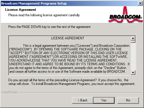
The Broadcom Advanced Control Suite (BACS) can be installed from the Dell CD-ROM, or by using the silent install option.
Broadcom recommends that you copy the installation files to your hard disk before running the silent install. This is because the setup bacs command automatically generates a setup.log file in the directory it is run from. When the silent install is run from the CD, it cannot generate this log file, and the setup install fails.
Copy the the MgmtApps directory from the Dell CD-ROM to your hard disk.
|
NOTE
If the silent install MUST be run from the CD, the command . . .
setup bacs /f2"c:\setup.log" . . . will target c:\ for an
alternative log file location. |
|
NOTE To silent install BASP, enter "setup BACS BASP". |
|
NOTE Before installing on Windows 2000 Advanced Server with Terminal Services, the command "change user /install" must be issued, otherwise an error will occur. |
Insert the Dell CD-ROM into your systems CD-ROM drive.
Control Suite - Check this box to install the Advanced Server Control Suite.
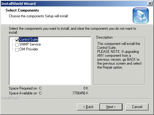
SNMP Service - Check this box to install the Advanced Server SNMP sub-agent.
| NOTE The Microsoft SNMP Service must be running for this component to function properly. |
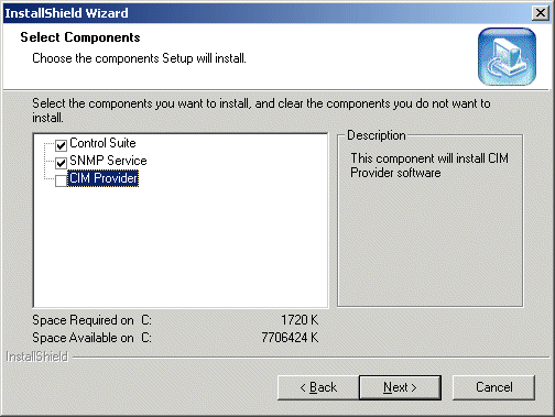
CIM Provider - Check this box to install the CIM Provider.
Click Next. The selected program(s) will be installed.
A Windows dialog box will appear. Click Yes to install the Broadcom Advanced Server Program (BASP) driver. Click No if BASP teaming software is not required.

When complete, an information screen as shown below will notify you that the files were successfully installed.

The Control Suite can be started from the Control Panel by double-clicking the Broadcom Control Suite icon.
To update the BACS, do the following:
Insert the Dell CD-ROM into your systems CD-ROM drive.
Open the MgmtApps folder on the CD and double-click setup.exe. The Broadcom Management Programs Setup screen appears.
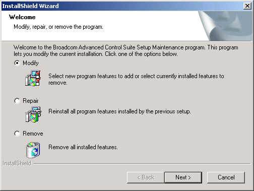
Click the Modify radio button and click Next.
Control Suite - Check
this box to install the Advanced Server Control Suite.
SNMP Service - Check
this box to install the Advanced Server SNMP sub-agent.
CIM Provider -
Check this box to install the CIM Provider.
Click Yes to install the Broadcom Advanced Server Program (BASP) driver.
Click No if BASP teaming software is not required.
When complete, an information screen as shown below will notify you that the files were successfully installed.
Note that the Control Suite can
be started from the Control Panel by double-clicking the Broadcom Control
Suite icon.
To remove the Broadcom Advanced Control Suite (BACS) software, perform the following:
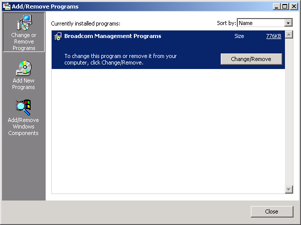


| NOTE This does not uninstall the BASP. |
To initialize the Broadcom Advanced Control Suite (BACS) software, do the following:
|
NOTE The Broadcom NetXtreme™ Gigabit Ethernet Adapter must be enabled before initializing the BACS. Refer to "Installing the Driver Software" for the operating system that you are using. |
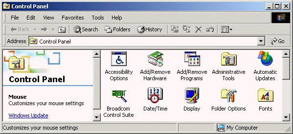
| NOTE Broadcom Control Suite can also be started from the system tray icon. |
The Vital Sign screen allows you to view vital adapter information, network status, and network connectivity. Active adapters are listed in the Installed Adapters window. When selected, vital sign information for that adapter is displayed.
| NOTE Information for Non-Broadcom adapters is less comprehensive than information listed for Broadcom adapters. |
Interface components of the BACS Vital Sign window are described below:
Example: [0] 14 indicates Broadcom adapter resides in PCI bus 0, device 14.
1000 Mbps Full Duplex
Interrupt: This parameter indicates the interrupt line number that is associated with the selected adapter. The valid number is ranged from (2 - 25).
Memory
Address: This parameter indicates the memory mapped address that is assigned
to the selected adapter. This value can never be zero.
ASIC/Firmware Version: This field displays the Chip and Firmware versions of the selected Broadcom adapter.
| NOTE Only adapters with a 1000 Mbps link will light the Gigabit Receive OK and Gigabit Transmit OK LEDs. |
| NOTE Parameters (3 through 10) are not applicable on other vendor's adapters and these values are displayed as: Information Not Available. |
| NOTE The Gigabit Receive OK and Gigabit Transmit OK LEDs will not appear for other vendor cards. |
The Network Test allows you to verify IP network connectivity. This test verifies if the NDIS driver is installed correctly and test connectivity to a gateway or other specified IP address on the same subnet. The Network test supports TCP/IP.
The Diagnostics screen allows you to view information only for Broadcom adapters. This function is used to test the physical adapter components.
| NOTE Network connection will be lost when running these tests. |
Interface components of the BACS Diagnostics window are described below:
Control Registers Test
- This test verifies the read and write capabilities of the network controller
registers by writing various values to the registers and verifying the
result. The device driver uses these registers to perform network functions
such as sending and receiving information. If the test fails, the network
adapter may not work properly.
MII Registers Test -
This test verifies the read and write capabilities of the physical layer
chip registers. The physical layer chip is used to control the electrical
signals on the wire and for configuring network speed.
EEPROM Test - This test
verifies the content of the EEPROM by reading a portion of the EEPROM
and computing the checksum. The test fails if the computed checksum is
different than the checksum stored in the EEPROM.
Internal Memory Test
- This tests verifies that the network controller internal memory is functioning
properly. The test writes patterned values to the memory and reads back
the results. The test fails if an erroneous value is read back. The network
controller will not function without its internal memory.
On Chip CPU Test - This
test verifies the operation of the two internal CPUs in the network controller.
Interrupt Test
- This test verifies that the NDIS driver is able to receive interrupts
from the network controller.
MAC and PHY Loopback Test - These tests verify that the NDIS driver is able send packets and receive packets from the network controller.
Test LED - This test
blinks all LEDs five times to identify the adapter.
From the Cable Analysis screen, the user can monitor conditions of an Ethernet CAT5 cable connection within a cable plant in an Ethernet network. The software measures the cable quality and compares it against the IEEE 802.3ab for compliance. Given a graphical environment, it can display the frequency-response characteristics of each cable pair.
The Cable Analysis screen allows you to display the "Gain vs. Frequency Characterization" feature.
| NOTE Network connection will be lost when running this test. |
The Length sub tab allows you to verify cable length, which is calculated by a Return Loss algorithm, and determine whether your configuration has the appropriate cable. This utility allows you to determine whether the problem is with the adapter or in the cable plant.
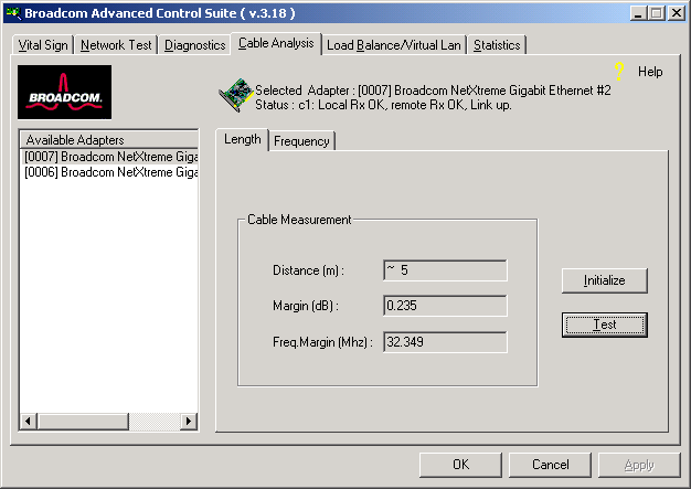
Interface components for the BACS Cable Analysis/Channel Pairs window are described below:
Distance: This field presents the estimated cable length in meters by averaging all four channels using Return Loss algorithms. The unit is in meter (m).
Margin: Margin yields the minimum distance between the measured cable pair and the maximum IEEE 802.3ab limits. The unit is in dB.
Each channel's frequency response is displayed based on the computation by the cable algorithms. The two graphs represent the values calculated by the Cable Loss and Return Loss algorithms. The vertical axis represents the gain in dB and the horizontal axis represents the operating frequency. The blue graph is the IEEE 802.3ab limit and the red graph is the actual computed values for a particular twisted pair. The two methods of measurement present the typical measurement standards to characterize the cable quality. It is important to take both measurements into consideration, as one result alone is not indicative of the characterization of the cable being tested.
From the Cable Analysis/Frequency screen, select the Broadcom adapter and channel to be tested.
Click Initialize, then click Test to display the status of the selected adapter.
The cable loss (red) curve represents the insertion loss of the cable under test as a function of frequency in the frequency range [0 - 62.5 MHz]. The cable loss limit (blue) curve represents the cable loss limit as specified in Section 40.7.2.1 of the IEEE Standard 802.3ab-1999. The cable loss curve (red) on top of the cable loss limit (blue) curve indicates the cable is within the operating limit. If the cable loss (red) curve superimposes the cable loss limit (blue) curve, the cable is marginal to the operating limit. If the cable loss (red) curve is below the cable loss limit (blue) curve, the cable is outside the operating limit of the IEEE 802.3ab-1999 standards. This condition would signify that the cable length is too long and not operational.
The return loss (red) curve represents the return loss of the cable under test as a function of frequency in the frequency range [0,62.5 MHz]. The return limit (blue) curve represents the return loss limit as specified in Section 40.7.2.3 of the IEEE Standard 802.3ab-1999. The return loss (red) curve below of the return limit (blue) curve indicates the cable is within the operating limit. If the return loss (red) curve superimposes the return limit (blue) curve, the cable is marginal to the operating limit. If the return loss (red) curve is above the return limit (blue) curve, the cable is outside the operating limit of the IEEE 802.3ab-1999 standards. This condition would signify that the cable length is too long and not operational.
The Load Balance/Virtual LANs screen allows you to configure advanced features. Any available adapter can be configured as part of a team. Teaming is a method of grouping multiple adapters into a virtual adapter (bundling multiple adapters to look like a single adapter). The benefit of this approach is load balancing and redundancy, see "Teaming Overview".
An example of this usage using the graphic provided below shows two available adapters on the primary side. By selecting each of the available adapters, and moving each of them over to the Load Balance Members field, they then appear to the outside world as one adapter. Each member in the Load Balance Member list shares the traffic burden of all members.
The Standby Member field is used to permit the selection of one of the team members to handle traffic, should all members in the Load Balance Member list fail (failover). The selected Standby Member will not handle any traffic unless all Load Balance Members fail. When one Load Balance Member (or more) is restored (fail-back), traffic will then be handled by the restored team member(s).
Right-click on the node of Load Balance tree to display a drop-down menu that is associated with the selected node type.
For the team node, the menu items are Delete and Properties. The user can either select Delete to remove the highlighted team or Properties to display the Team Properties dialog box.
From the Team Properties dialog, the user can change team name and/or change the team type.
For the adapter node, the menu items are Unassign and Properties. The user can select Unassign to remove the selected adapter from the team orProperties to display the adapter Properties. All display in adapter Properties are read-only.
For the VLAN node, the menu items are Delete andProperties. The user can either select Delete to remove the highlighted VLAN orProperties to display the VLAN Properties. The only writable item on this dialog box is VLAN name.
A team is comprised of at least one primary adapter (a standby adapter is optional). Each adapter can belong to only one team. To create a new team perform the following steps:
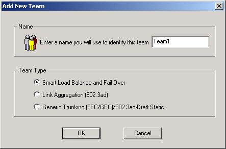
Enter a team name in the "Name" entry field (i.e., Team1), then select the Team Type and click OK.

| NOTE At least one adapter must be displayed in the Load Balance Members list box. |
| NOTE The minimum number of characters that can be used in a team name is one, and the maximum number of characters that can be used in a team name is 39. A Team Name cannot begin with spaces nor contain the character "&". If you attempt to use an identical team name, an error message displays indicating that the entered name already exists. The maximum number of members in a team is eight. |
When you create a generic trunking team, you cannot select a Standby Member. Standby Members only work with Smart Load Balance and Failover Teams.
| NOTE Only one Standby Member is allowed when using Smart Load Balance and Failover Teams.. |
| NOTE Not all vendor adapters are supported or fully certified for Teaming. If an adapter is not (fully) supported, you can click List All Supported Adapters to display a list of fully supported adapters. |
To set an adapter's IP address, use the following menu:
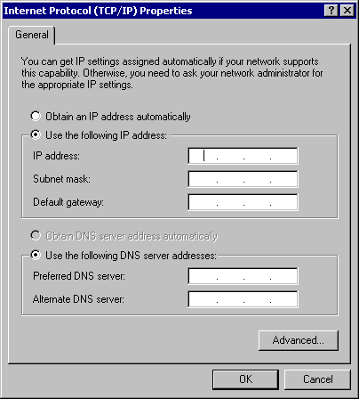
To remove an adapter from its assigned team, select the adapter in the Load Balance Members list and click the arrow key. The adapter will be removed from the Load Balance Members list and will reappear in the Available Adapters list.
To delete a configured team and release its assigned adapters, select the team you want to delete, and click the Remove Team button. The team and all its assigned adapters will be removed from the team list. The released adapters will reappear in the Available Adapters list.
| NOTE Adapters that are part of a team inherit all the basic configuration properties of the team, including VLANs associated with the team. If you delete a Team, any VLANs configured for that team will also be deleted. |
You can add VLANs to a team. The concept behind this is that you are adding multiple virtual adapters that are on different subnets. The benefit of this is that your server can have one NIC that can belong to multiple subnets. With a VLAN you can couple the functionality of load balancing for the Load Balance Members and you can employ a failover adapter.
You can define up to 64 VLANs per team (63 tagged and 1 untagged). VLANs can only be created when all members are Broadcom adapters. If you try to create a VLAN with a non-Broadcom adapter, an error message displays.
| NOTE Disabled Broadcom adapters are not recognized and will not allow the creation of a VLAN. If you attempt to create a VLAN with a disabled Broadcom adapter, the error message above will appear. |
To configure a new VLAN, perform the following steps:
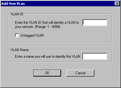
The Untagged VLAN checkbox is exclusively used by the VLAN ID field. To use VLAN ID zero, simply check this box.
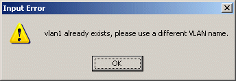
If you enter a VLAN name or ID and the name already exists, an Input Error message is displayed similar to the one below:
| NOTE To maintain optimum adapter performance, your system should have 64 MB of system memory for each eight VLANs created per adapter. |
The Create VLAN button can also be used to create a team with a VLAN. To utilize this method:
Click the Create VLAN Button
Enter a VLAN ID and a VLAN Name then click the Next button.
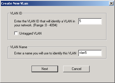
A list of Avaliable Adapters are shown. These adapters are not currently
members of any team.
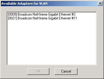
Select an adapter and click OK.
Click OK or Apply to save the changes.
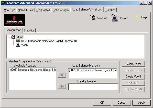
| NOTE If you delete a Team, any VLANs configured for that team will also be deleted. |
To delete a configured VLAN, perform the following steps:
To save a configuration, perform the following:

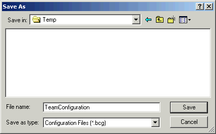
A configuration file will be placed in the directory as shown below.
This new configuration file is a text file and can be viewed by any text editor. As shown below, it contains both adapter and team configuration information.
To restore a saved configuration, perform the following:
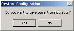
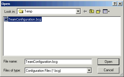
NOTE The Open screen will navigate to the folder where the last configuration file was stored. If the configuration file to be restored is elsewhere, navigate to that location to select the file.

The following shows the screen that displays when you select the Statistics tab.
The Statistics screen allows you to view traffic statistics for both Broadcom and non-Broadcom adapters. Statistical values and coverage is more comprehensive for Broadcom than for non-Broadcom adapters.
| NOTE If a Broadcom adapter is disabled, its team will not be displayed in the Statistics window. |
Interface components of the BACS Statistics/General tab window are described below:
Interface components of the BACS Statistics/IEEE 802.3 tab window are described below:
| NOTE The Custom tab will only appear for an enabled Broadcom adapter. |
A complete view of Interface components of the BACS Statistics/Custom tab window are shown below. Their descriptions follow: