Back to Contents Page
Dell™ Remote Access Controller
Installation and Setup Guide
This section provides information specifically about DRAC III. It includes a list of DRAC III features, DRAC III kit contents, supported systems, hardware and optional hardware installation instructions, and a software configuration overview.
 |
NOTE: Throughout the remainder of this document, the system in which the RAC is
installed or embedded is referred to as the managed system. A system that remotely
accesses the RAC is referred to as a management station. The term system console
refers to a system's keyboard, mouse, and monitor.
|
The DRAC III is a 33-MHz PCI card with its own microprocessor and memory. The DRAC III may be preinstalled on your system, or available separately in a kit. To get started with a DRAC III that is already installed on your system, see "Software Installation and Configuration Overview." If the DRAC III is not already installed on your system, see "Installing the DRAC III Hardware" before beginning the software installation and configuration.
In addition to the features listed in "Remote Access Controller Features," the DRAC III also provides the following features:
- Ability to manage and monitor the managed system through the DRAC III NIC and the optional modem and serial port (using the optional VT-100 cable).
- Console redirection, which can be performed using the DRAC III NIC, optional modem, or serial port (using the optional VT-100 cable).
|
NOTE: The serial connection supports text-only console redirection.
|
- A battery backup that provides power to the DRAC III for up to 30 minutes in the event of a power failure.
- An external AC power adapter that allows the DRAC III to function when the system is off.
|
NOTE: While the DRAC III does not require an external power adapter, using one will
allow the DRAC III to remain operational when the system is off, and will extend DRAC III
power beyond the 30-minute limit of the battery backup.
|
- A PCMCIA modem socket for the optional modem.
- In addition sending alerts in the form of an e-mail message or an SNMP trap (through the integrated NIC), the DRAC III also sends alerts as numeric or alphanumeric pages.
- On 64-bit systems, the DRAC III is equipped with a 3-pin cable that allows access to the system's IPMB. The IPMB provides remote monitoring, log in, and recovery control functions independent of the system's main processors, BIOS, and operating system. The IPMB is available for remote monitoring even when the system is off.
In addition to the security provided for the RAC NIC and Web-based interface connections (see "Remote Access Security Features"), the DRAC III also provides security for VT-100 and modem connections.
Password encryption is not used for this type of connection because the VT-100 connection is a direct-connect terminal emulation, and as such, does not warrant encryption. Terminal security is provided by nonencrypted authentication of the user name and password. The firmware prevents display of the password on the terminal. System power management features (such as reset and power cycle) and text console redirection are provided through the VT-100 interface. Access to a graphical operating system is not available.
DRAC III supports CHAP encryption for PPP modem connections.
- DRAC III hardware
- IPMB cable (64-bit systems only)
- External power adapter and power cable (only in countries where certified)
- VT-100 cable (optional)
- Riser board with two PCI slots (Dell™ PowerEdge™ 1650 only)
- Dell OpenManage Server Assistant CD
- Dell OpenManage Systems Management CD (or Server Management CD for 64-bit systems)
- Product Documentation CD (or Documentation CD for 64-bit systems)
DRAC III supports the following PowerEdge systems: 1650, 4600, 6600, 6650, and 7150 systems.
|
NOTE: See your racread.txt file for the most current list of supported systems.
|
DRAC III supports the following PCMCIA modems:
- ActionTec (U.S. and Canada only)
- Psion Gold Card (56K and fax)

|
CAUTION: Before you perform this procedure, you must turn off the system and disconnect it from its power source. Only trained service technicians are authorized to remove the system cover and access any of the components inside the system. Read and follow all safety precautions in your System Information Guide. |
 |
NOTICE: Before installing a DRAC III, read the installation instructions in this document and
in your system's Installation and Troubleshooting Guide.
|
- Turn off the system and all attached peripheral devices.
- Disconnect the system and peripherals from electrical outlets. Disconnect any
telephone or telecommunication lines from the system.
|
|
CAUTION: Only trained service technicians are authorized to remove and access any components inside the system. See your System Information Guide for complete information about safety precautions, working inside the computer, and protecting against electrostatic discharge. |
- Before touching anything inside the system, touch an unpainted metal surface at the
back of the system chassis to dissipate any static electricity that might harm internal
components.
|
NOTICE: Failure to dissipate static electricity may damage or destroy static-sensitive
components.
|
- Remove the system cover according to the instructions in your system's Installation
and Troubleshooting Guide.
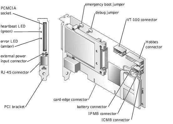
- If your DRAC III kit included a PCMCIA modem, insert the modem into the
PCMCIA socket on the DRAC III PCI bracket. See Figure 2-1 for component
locations.
Figure 2-1. DRAC III Hardware Components
- Press firmly to seat the modem card into the socket, ensuring that the pins are properly
seated in the connector.
- Connect the modem cable to a telephone jack.
|
NOTICE: If you are installing the DRAC III on a 32-bit system, skip steps 8 and 9. If you are
installing the DRAC III on a 64-bit system and want access to the IPMB, you must complete
steps 7 and 8 before installing the DRAC III into the system. If you are not sure if your system is
equipped with an IPMB connector, see your system documentation.
|
- Plug the IPMB cable into the 3-pin yellow IPMB connector on the DRAC III. See
Figure 2-1.
Ensure that the cable is securely connected to the DRAC III card.
- Plug the free end of the IPMB cable into the 3-pin connector on the system backplane.
See your system Installation and Troubleshooting Guide for the location of this connector.
- Insert the DRAC III into PCI slot 1.
|
NOTICE: For the DRAC III to function properly, it must be installed in the 32-bit, 33-MHz
PCI slot 1. The DRAC III must be inserted into PCI slot 1 because it must reside on the same
bus as the video controller. If another expansion card is installed in slot 1, it must be moved to
another slot before proceeding with the installation.
|
|
NOTICE: On PowerEdge 1650 systems, the DRAC III is installed on a riser board. The riser
board plugs into the riser connector on the system board and is considered an extension of the
system board. The riser board is equipped with one 32-bit, 33-MHz expansion slot (PCI1) for 5-
V cards, and one 64-bit, 66-MHz expansion slot (PCI2). For the DRAC III to function properly,
it must be installed in the 32-bit PCI1 slot. If you purchased the DRAC III with your PowerEdge
1650, the riser card and the DRAC III are preinstalled. If you purchased the DRAC III kit
separately for installation on a PowerEdge 1650, see the instructions for installing the riser
card contained in the kit.
|
Ensure that the card-edge connector is fully seated into the system board.
- If your DRAC III kit includes the optional VT-100 serial cable, connect it to the
VT-100 serial connector on the DRAC III (see Figure 2-1), and then install the cable's
external port into an empty slot in your system. For more information about using a
VT-100 connection, see the document included in your VT-100 serial cable kit.
|
NOTICE: You must use the DRAC III VT-100 serial cable specifically provided for use with the
DRAC III because not all serial cables have the same pin-out specification. Using the wrong
cable will result in VT-100 terminal emulation failure or DRAC III failure.
|
- Follow the instructions in your system Installation and Troubleshooting Guide to
reassemble the system and replace the system cover.
- Connect the external power adapter to a UPS or available power receptacle. For power
supply specifications, see "Power Requirements."
|
NOTE: While the DRAC III does not require an external power adapter, using one allows
the DRAC III to remain operational when the system is off, and extends the DRAC III
power beyond the 30-minute capability of the battery pack.
|
|
NOTE: A UPS is recommended for the most complete power protection.
|
- Connect the power jack to the external power input connector on the DRAC III PCI
bracket.
- If you are using a network connection with the DRAC III, attach the twisted-pair cable
to the RJ-45 connector on the DRAC III. See Figure 2-1 for location of these
connectors.
|
NOTE: The maximum length allowed for the LAN cable connected to the RJ-45 connector is 184 ft (56 m).
|
- If you are going to use the optional modem with the DRAC III, attach a modem
adapter cable to the PCMCIA modem socket. Next, connect the adapter cable to an analog telephone line.
- Reconnect any telephone or telecommunications lines to the system, and all
peripheral devices to their electrical outlets, and turn them on.
If the DRAC III installation was successful, the green heartbeat LED indicator on the back of the card connector is illuminated (see "DRAC III Hardware Components").
After completing the hardware installation procedures, you must install and configure the RAC software. For more information about the RAC software components, see "Software Components." For an overview of RAC software installation and configuration, see "Software Installation and Configuration Overview."
This section provides a high-level overview of the RAC software installation and configuration process for DRAC III. Some steps give you the option of using several different tools to perform the configuration, including Server Administrator, IT Assistant, the racadm CLI utility, and your operating system utilities.
For more information about the RAC software components, see "Software Components."
Depending on the tool used to perform the configuration, see the following documents for more information:
- Dell OpenManage Server Administrator User's Guide
- Dell OpenManage IT Assistant User's Guide
- Dell Remote Access Controller Racadm User's Guide
- Operating system documentation
To install and configure your RAC software, perform the following steps in their numbered order:
- Update the system BIOS. See "Updating the System BIOS."
- Install the software on the managed system. See "Installing the Software on the Managed System."
- Configure the RAC network settings. See "Configuring the RAC Network Settings."
- Add and configure RAC users. See "Adding and Configuring RAC Users."
- Configure the DRAC III optional modem. See "Configuring the DRAC III Optional Modem."
- Add and configure dial-in (PPP) users. See "Adding and Configuring Dial-in (PPP) Users."
- Configure dial-out alert notification on the management station. See "Configuring Dial-Out Alert Notification on the Management Station."
- Install (or upgrade) the software on the management station. See "Installing (or Upgrading) the Software on the Management Station."
- Configure the management station's modem. See "Configuring the Management Station's Modem."
- Configure the Web browser to connect to the remote access interface. See
"Configuring the Web Browser to Connect to the Remote Access Interface."
- Connect to the remote access interface. See "Connecting to the Remote Access Interface."
- Use (optional) the racras.ini file to configure dial-up networking used by the IT
Assistant software.
If you are adding a RAC to an existing managed system, it is recommended that you update the system's BIOS before installing the RAC to ensure full support for the card. See "Updating the System BIOS."
Install the software on the managed system using the Systems Management CD (32-bit systems) or the Server Management CD (64-bit systems).
For instructions on installing this software, see your Server Administrator User's Guide.
The managed system has the following components embedded or installed: the RAC, the appropriate version of Server Administrator, and the appropriate RAC agent. Depending on the operating system, the RAC agent consists of either Microsoft® Windows® services, Novell® NLMs, or Red Hat Linux drivers and daemons. The RAC agent automatically starts when you boot the managed system.
|
NOTE: If you are configuring the DRAC III on a 64-bit system, you must install the
DRAC III drivers. For more information, see "Installing DRAC III Drivers on 64-Bit Systems."
|
Configure the RAC network settings using one of the following tools:
Add and configure RAC users using one of the following tools:
- Server Administrator
- racadm CLI utility
If your DRAC III includes the optional modem, configure the modem on the DRAC III using one of the following tools:
- Server Administrator
- racadm CLI utility
Add and configure dial-in (PPP) users using one of the following tools:
Configure dial-out alert notification on the management station using one of the following tools:
If necessary, install (or upgrade) the software on the management station, including Server Administrator and IT Assistant, using the Systems Management CD (32-bit systems) or the Server Management CD (64-bit systems).
For instructions about installing this software, see your Server Administrator User's Guide.
A management station is a system (typically a workstation running Windows 2003 or Windows 2000) that has the following components installed: appropriate versions of Server Administrator (or IT Assistant), a supported Web browser (for more information, see "Supported Web Browsers"), Windows services (if applicable), Server Administrator (or IT Assistant) services, and user interface elements.
To use the management station's modem for remote access to a DRAC III, you must configure the management station's modem. See "Changing the PPP Server IP Address on the Managed System" for instructions.
If you are using a client system that connects to the Internet through a proxy server to connect to the RAC Web-based remote access interface, you must configure your Web browser for this connection.
See "Configuring a Web Browser to Display the Remote Access Interface."
To connect to the remote access interface through the network connection, see "Connecting to the Remote Access Interface." To connect to the interface through the DRAC III optional modem, see "Accessing a DRAC III Through a Modem." To connect to the DRAC III through the optional VT-100 serial connection, see "Accessing the DRAC III Remote Access Interface Using VT-100 Terminal Emulation."
The racras.ini file is used by DRAC III remote access dynamic link library (DLL) functions and the proxy server to provide user-specified configuration. Generally, the contents of the racras.ini file do not have to be modified. The file is for advanced user configuration only.
Modify the racras.ini file to tune the interactions between the RAC and IT Assistant for specific requirements of your user environment.
|
NOTE: You must reboot the system for modifications to the racras.ini file to take
effect.
|
The following entries are included in the racras.ini file:
Enable Proxy Routing – This entry allows users to disable proxy routing. If proxy routing is disabled, only a user with a browser running on the IT Assistant host system is able to connect to the DRAC III. The connections do not require the DRAC III remote access service proxy server, so the proxy server is disabled. Enable the proxy server when a browser is running on managed systems other than the IT Assistant services host system.
- True (Enabled) – Browser running on a system other than the IT Assistant services host.
- False (Disabled) – Browser running on the IT Assistant services host.
DRAC III Web Server Port (specified port number) – This entry is the port number that the DRAC III Web server monitors for new Web connections. When the proxy server connects to a DRAC III, it uses this port.
|
NOTE: The default port is 80. Change the default only if it is modified on the DRAC III.
|
Max Number of Routes to Proxy – This variable identifies the maximum number of users that can be routed by the remote access service proxy server at one time.
Max Number of Routes to Proxy + Base Port Number – This variable is the sum of the base port number and the maximum number of users that can be routed by the remote access service proxy server at one time.
|
NOTE: The default port is 0. This default means that available ports are identified by the
operating system. Change the default only if specific ports are already in use.
|
Base Port Number for UI-side Ports – This entry is the starting port number that the remote access service proxy server uses for incoming port connections from the DRAC III Web-based interface. Two ports are used per route; therefore, the remote access service proxy may use the ports ranging from this base number up to the maximum number of routes to proxy.
Proxy IP Address – If you need to use a different IP address on the incoming IT Assistant services host system than the one currently used by the standard services host, then enter that address.
|
NOTE: Set this entry to 0 if it is not being used. Use the entry only if the managed system
has multiple IP addresses.
|
In addition to RAC users (see "RAC Users"), the DRAC III also supports the following users and entries:
- DRAC III dial-in users – Also called point-to-point protocol (PPP) users, dial-in user names and passwords are used to establish a dial-in connection only. After the connection is established, a RAC user name and password must be supplied to perform console redirection, configuration, and management actions.
- Demand dial-out entries – Demand dial-out entries specify a destination IP address, the telephone number of a management station, a management station user name and password, and the authentication type associated with the management station user name and password.
|
NOTE: The demand dial-out entries are not RAC users. Rather, they are remote
management station users.
|
|
NOTE: It is not necessary for the destination IP address to be the remote management
station that answers the telephone. The destination IP address may be the IP address of
another remote management station. If the destination IP address is the IP address of
another remote management station, the management station answering the telephone must
be able to route to the destination IP address specified.
|
Some of the DRAC III features are configured within the context of a RAC user, such as alerting and paging. The following sections describe how to configure the DRAC III features and/or users outside of the Server Administrator environment.
To provide client access to the DRAC III, you must add and configure dial-in (PPP) users. For information about configuring these users in Server Administrator, see your Server Administrator User's Guide. For information on configuring these users in IT Assistant, see your IT Assistant User's Guide. Otherwise, use the procedures in the following sections to add and configure dial-in users.
|
NOTE: It is also possible to use the racadm command-line utility to add and configure
dial-in users. For more information, see the Racadm User's Guide.
|
|
NOTE: If for any reason all the DRAC III users are deleted, use the racadm command-
line utility to create new users.
|
The DRAC III provides network support through two different interfaces: the DRAC III NIC, and the optional PCMCIA modem. As a result, it is possible that a network loop could be created when both connections are active. This loop makes it difficult for the DRAC III to communicate with its Windows correspondent.
To access the management station from the DRAC III through two distinct paths, you must assign a demand-dial route to the DRAC III from the managed system that does not conflict with the network-based local LAN route.
To assign this demand-dial route, perform the following steps:
- Configure dial-up networking on the management station to assign static IP addresses
for dial-in purposes. This configuration requires two addresses: one for the
management station and one for the DRAC III.
|
NOTE: It is important that the static IP addresses used by the management station be on a
different subnet from the DRAC III NIC.
|
Typically, the address that is numerically lower is assigned to the management station and the higher address is assigned to the DRAC III when the dial-in connection is complete.
- Configure the management station's static IP address as the demand-dial destination
IP address on the DRAC III. Then configure this same address on the DRAC III as an
SNMP trap destination (for SNMP trap alerts), or as the SMTP server address (for e-
mail alerts).
|
NOTE: If you use DHCP to assign these IP addresses, you must ensure that both addresses
used by the management station for dialing-in are on a different subnet from the DRAC III
NIC.
|
The management station is now able to receive alerts from the DRAC III through both the network and the dial-in connection.
- Ensure that dial-up networking is installed.
- Click the Start button, point to Settings, and click Control Panel.
- Click the Add/Remove Programs icon.
- In the Add/Remove Programs Properties dialog box, click the Windows Setup tab,
select Communications in the list, and then click Details.
- In the Communications dialog box, ensure that Dial-Up Networking and Phone
Dialer are selected (checked). If not, install these components.
It may be necessary to download msdun13.exe from the Microsoft website for Windows 95; this file contains patches that enhance dial-up networking.
- Return to the Control Panel and click the Network icon.
- On the Configuration tab, ensure that Client for Microsoft Networks, Dial-Up
Adapter, and the TCP/IP options are installed. If not, install the components by
performing one or both of the following:
- If the Dial-Up Adapter option is missing, click Add; next, in the Select Network Component Type dialog box, click Adapter.
- If the TCP/IP option is missing, click Add; next, in the Select Network Component Type dialog box, click Protocol.
- In the Network dialog box, select TCP/IP® Dial-Up Adapter, and then click
Properties.
The properties in the TCP/IP Properties dialog box must remain at their defaults. Confirm the following settings:
- On the IP Address tab, ensure that Obtain an IP Address Automatically is selected.
- On the WINS Resolution tab, ensure that Disable WINS Resolution is selected.
- On the Gateway tab, ensure that New gateway is blank.
- In the TCP/IP Properties dialog box, click OK.
- In the Network dialog box, click OK.
- Close the Control Panel window.
- Click the Start button, point to Programs, point to Accessories, and click Dial-Up
Networking.
- In the Dial-Up Networking dialog box, click Make New Connection and type in the
modem, name of the DRAC III, and telephone number of the DRAC III.
- After you make the new connection, right-click on the connection and click
Properties.
- Click the Server Types tab, and ensure that only TCP/IP is selected (checked).
- Click TCP/IP Settings and ensure that only Server Assigned IP address, Server
Assigned Name Server Addresses, and Use IP Header Compression are selected
(checked).
|
NOTE: The following instructions vary slightly depending on the system's Windows
2000 configuration.
|
- Click the Start button, point to Settings® Control Panel® Network and Dialup
Connections, and click Make New Connection.
- Click Next.
- Select Dial-Up to a private network.
- Click Next.
- Enter the telephone number of the DRAC III to which you want to connect.
- Click Next three times.
- Type a name for this connection.
- Click Finish.
- Click the Start button, point to Settings® Control Panel® Network and Dialup
Connections, right-click the connection you just created and named, and select
Properties.
- Click the Networking tab.
- Ensure that Type of dial-up server I am calling is set to PPP: Windows 95/98/2000,
Internet.
- Ensure that Internet Protocol (TCP/IP) is checked.
- Click Properties.
- Click Advanced.
- Deselect (clear) Use default gateway on remote network.
- Click OK twice.
- Click the Security tab.
- Ensure that Allow Unsecured Password is selected (different service pack versions of
Windows 2000 may move this option around, refer to it as Clear Text, or present it as
a check box; ensure that you find this option and select it).
- Click OK.
- Reboot your system.
- Click the Start button, point to Control Panel® Network Connections, and click New
Connection Wizard.
- Click Next.
- Select Connect to the network at my workplace and click Next.
- Select Dial-up connection and click Next.
- Enter a name in the Company Name field and click Next.
- Enter the telephone number of the DRAC III to which you want to connect and click
Next.
- Select Anyone's use and click Next. If you only want the current user account to be
able to use the dial-in connection, select My use only.
- Click Finish. Create a shortcut on your desktop if you want one.
- Click the Start button, point to Connect To, and then click the connection you just
created and named.
- Click Properties.
- Click the Security tab.
- Ensure that the Allow Unsecured Password option is selected.
- Click OK.
- Click the Networking tab.
- Click Properties.
- Click Advanced.
- Deselect (clear) the Use default gateway on remote network option and click OK.
- Enter the IP address for the PPP adapter.
To find the IP address for the PPP adapter, open a command prompt and type ipconfig, and locate the IP address under PPP adapter.
- Click OK.
- Ensure that Type of dial-up server I am calling is set to PPP: Windows
95/98/NT4/2000, Internet.
- Enable the Internet Protocol (TCP/IP) field and click OK.
- Reboot your system.
|
NOTICE: Before beginning this procedure, PPP must first be configured and installed on the
client system. PPP-2.3 or later is available from the Red Hat website at www.redhat.com.
|
- Download and configure the latest PPP (2.3.11 or later) source code.
- Read the readme.cbcp file included in the PPP software distribution.
- Apply the patch included in the readme.cbcp file, and then make and install as usual.
- To test whether your PPP daemon supports the callback protocol, open a command
shell and issue the following command:
pppd callback 1111
If your PPP daemon is not properly configured, it generates an error message about the callback option.
- After verifying that your PPP daemon is configured with callback support, you must
set up the proper chat scripts for your environment.
An example modem setup is described at
www-cache.mppmu.mpg.de/callback/linuxanalog.html.
- Create the file /etc/ppp/peers/rac with the following contents:
tty02 crtcts 38400
connect `chat –v –f /etc/ppp/chat/rac'
noipdefault
nodefaultroute
lock
user <username>
remotename <rac>
where <username> is the DRAC III user name that is supplied to the DRAC III, and <rac> is the name preferred for the DRAC III.
- Create the file /etc/ppp/chat/rac with the following contents, where the actual
telephone number replaces 555-1212.
This chat script assumes a modem with a standard AT command set and may need to be modified if the actual modem does not support this command set:
ABORT "NO CARRIER"
ABORT "NO DIALTONE"
ABORT "ERROR"
ABORT "NO ANSWER"
ABORT "BUSY"
"" "at"
OK "at&d2&d1"
OK "atdt555-1212"
- Edit the /etc/ppp/chap-secrets file (which lists PPP users and passwords) to include
the DRAC III PPP user.
Using the following example as a guideline, add a single line to the file.
|
NOTE: The <username> and <rac> values in the following example must match the
<username> and <rac> values placed in the /etc/ppp/peers/rac file in step 7.
|
# client server secret IP addresses
<username> <rac> <password> *
where <password> is the password that is supplied to the DRAC III during the authentication phase of PPP negotiation.
|
NOTE: The IP address value (indicated by the * symbol in the previous example) is not
used when acting as a PPP client.
|
For DRAC III dial-out alert notifications, you can specify a single SMTP system for receiving e-mail with up to eight SNMP trap destinations. When you specify the IP address of the SMTP system or any of the SNMP trap addresses in a demand dial-out entry, the DRAC III dials the telephone number specified in the demand dial-out entry to deliver an e-mail or SNMP trap to the SMTP system or SNMP trap addresses. If you do not specify the IP address of the SMTP system, or any of the SNMP trap addresses in a demand dial-out entry, the DRAC III NIC is used to deliver the e-mail or SNMP trap to the SMTP system or SNMP trap addresses.
To support the dial-out notification feature on the DRAC III, the management station must allow for dial-in. See the following sections for instructions about configuring dial-out alert notifications.
To configure your Windows 2000 management station so that the DRAC III can establish a connection and log an alert, you must add a new local user.
To add a new local user, perform the following steps:
- At the management station, click the Start button, point to Settings® Control Panel®
Users and Passwords.
|
NOTE: You must be logged on as an administrator to access this setting.
|
- From the Users and Passwords window, click the Advanced tab, and then click
Advanced.
- Under Local Users and Groups, click Users, and then click Action.
- Click New User.
- In the New User window, type in a Username, Password, and Confirm Password.
- Ensure that the User must change password at next login check box is not selected.
- Select the Password Never Expires check box.
- Click Create to create the new user.
- Click Close.
To enable a Windows Server 2003 management station to a receive and log an alert from a DRAC III, you must add a new local user to the management station by performing the following steps:
- Log on with administrator privileges.
- Click the Start button and select Administrative Tools and then click Computer
Management.
- Click the + sign to expand Local Users and Groups.
- Select the Users folder.
- Click Action at the top of the screen and select New User.
- Enter your new user information in all of the fields and click Create.
- Click Close.
If you want to use the modem on your management station to dial-up the DRAC III, you must first configure the management station's modem. The following sections provide instructions for configuring the modem on Windows 2000 and Windows Server 2003 management stations.
- Click the Start button, point to Settings, point to Control Panel, and double-click
Phone and Modem Options.
- In the Phone and Modem Options dialog box, click the Modems tab, and click Add.
- Follow the instructions in the Add/Remove Hardware Wizard.
- Repeat steps 2 and 3 for each modem you want to install.
- To configure a dial-up connection, click the Start button, point to Settings, click
Control Panel, double-click Network and Dial-up Connections, and double-click
Make new connection.
- Follow the instructions in the Network Connection wizard.
- To configure a dial-up connection, click the Start button, point to Control Panel®
Network Connections, and click New Connection Wizard.
- Follow the instructions in the New Connection Wizard.
When you connect to a DRAC III over a modem, the DRAC III functions as a RAS system by providing an IP address to the remote console. The DRAC III can obtain IP addresses using one of the following methods:
- Through a DHCP server, when DHCP is enabled
- From the base IP address, if it is not 0.0.0.0
- From a default IP address that is autogenerated by the DRAC III (ensuring that no two DRAC III cards have the same IP address)
|
NOTE: By default, the IP address is auto generated by the DRAC III on the 10.0.0.0
network.
|
The following sections provide instructions for accessing the managed system's DRAC III by modem from a previously-configured dial-in client. If you have not yet added and configured the client system for dial-in to the DRAC III, see "Changing the PPP Server IP Address on the Managed System."
- Click the Start button, point to Programs® Accessories, and click Dial-Up
Networking.
- In the Dial-Up Networking dialog box, double-click the connection that you created
and named in the "Configuring the Management Station Dial-Up Modem for DRAC III" section.
- Enter the user name and password for the DRAC III and click Connect.
- After the connection is accepted, open your Web browser and type the following
address:
http://<remote_IP_address>
where <remote_IP_address> is the DRAC III IP address.
If you do not know the IP address assigned to the DRAC III, you can calculate it by performing the following steps:
- Click the Start button, point to Programs, and click MS-DOS Prompt.
- At the MS-DOS® prompt, type the appropriate command for your operating
system:
If you are running Windows 95, type winipcfg.
If you are running Windows 98, type ipconfig.
- Press <Enter>.
- In the IP Configuration dialog box, click the down-arrow on the drop-down menu
and select PPP Adapter.
The IP Configuration dialog box does not display the remote IP address assigned to the DRAC III, but it does display the local IP address in the IP Address field.
- Calculate the DRAC III remote IP address by incrementing the PPP adapter IP
address by one.
- Click the Start button, point to Settings® Network And Dial-Up Connections, and
click the connection that you created and named in the "Configuring the Management Station Dial-Up Modem for DRAC III" section.
- In the screen displayed in step 1, type your user name and password if they are not
already there, ensure that any Domain box is deselected (unchecked), and click Dial,
Connect, or the equivalent.
- After the connection is accepted, open your Web browser and type in the following
address:
http://<remote_IP_address>
where <remote_IP_address> is the DRAC III IP address.
If you do not know the IP address assigned to the DRAC III, you can calculate it by performing the following steps:
- Click the Start button, point to Programs, and click Command Prompt.
- At the prompt, type the following command and press <Enter>:
ipconfig
The ipconfig command does not display the remote IP address assigned to the DRAC III, but it does display the local IP address.
- Calculate the DRAC III remote IP address by incrementing the IP address by one.
- Click the Start button, point to Connect To, and click the DRAC III connection that
you created and named in the "Configuring the Management Station Dial-Up Modem for DRAC III" section.
- In the screen displayed in step 1, type your user name and password if they are not
displayed, ensure that any Domain box is deselected (unchecked), and click Dial,
Connect, or the equivalent.
- After the connection is accepted, open your Web browser and enter in the following
address:
http://<remote_IP_address>
where <remote_IP_address> is the DRAC III IP address.
If you do not know the IP address assigned to the DRAC III, you can calculate it by performing the following steps:
- Click the Start button, point to Programs, and click Command Prompt.
- At the prompt, type the following command and press <Enter>:
ipconfig
The ipconfig command does not display the remote IP address assigned to the DRAC III, but it does display the local IP address.
- Calculate the DRAC III remote IP address by incrementing the IP address by one.
- Establish a connection to the DRAC III using the following command (where # is the
command shell prompt):
# pppd call rac
- After the connection is accepted, determine the IP address assigned to the DRAC III.
Both the local and remote addresses are logged in the system log as shown in the following example:
Apr 7 22:59:24 myhost pppd[187]: local IP address
10.19.250.93
Apr 7 22:59:24 myhost pppd[187]: remote IP address
10.19.250.94
In this example, you would type the following Web address into the address box of your Web browser:
http://10.19.250.94.
For information about using VT-100 terminal emulation with a DRAC III, including communication port settings, see the Information Update contained in your VT-100 serial cable kit.
To uninstall the DRAC III from your system, follow the instructions for installing the DRAC III at the beginning of this section, and then uninstall the components and cables in the reverse order that they were installed.
The following sections describe the replacement of the DRAC III battery, including removing and installing the battery pack.
|
|
Before removing or installing any system component, see the System Information Guide included with your system for important safety instructions. |
|
|
CAUTION: Before you perform this procedure, you must turn off the system and disconnect it from its power source. Only trained service technicians are authorized to remove the system cover and access any of the components inside the system. Read and follow all safety precautions in your System Information Guide. |
- Turn off the system and all attached external peripheral devices.
- Disconnect the system and its peripherals from power sources, and any telephone or
telecommunication lines from the system.
- Remove the system cover according to the instructions in your system's Installation
and Troubleshooting Guide.
- Touch an unpainted metal surface at the back of the system chassis before touching
anything inside the system.
- Remove the DRAC III from its slot.
- Disconnect the battery wire harness from the DRAC III.
- Remove the two screws from the battery housing.
- Squeeze the sides of the battery to release locking clips and remove.
|
|
CAUTION: Before you perform this procedure, you must turn off the system and disconnect it from its power source. Only trained service technicians are authorized to remove the system cover and access any of the components inside the system. Read and follow all safety precautions in your System Information Guide. |
- Insert locking clips into slots in the card, ensuring that the wire harness is toward the
top of the card.
- Attach the battery pack to the card using the two screws.
- Connect the battery wire harness to the header.
- Insert the DRAC III into the same slot from which it was removed and reattach
connectors or cables.
- Replace and secure the system cover.
- Reconnect the system and all associated external peripheral devices to power sources
and turn them on.
Back to Contents Page
 DRAC III Features